HowTo Guide for RapidSurf
Step-by-step tutorials for essential features and workflows
Selection Methods for Curves and Surfaces
RapidSurf provides two flexible methods for selecting and picking curves and surfaces, allowing you to choose the most convenient approach for your workflow.
- Method 1: Selection from Entity List: Access the entity dropdown list populated from the system storage. Simply click to expand the list and select the desired curve or surface from the available entities. This method is ideal when you know the entity name or want to select from a categorized list.
- Method 2: Direct Viewport Picking: Pick entities directly from the 3D viewport by left-clicking on the desired curve or surface. This visual selection method is intuitive and allows you to select exactly what you see in the scene.
Important Note for Viewport Picking
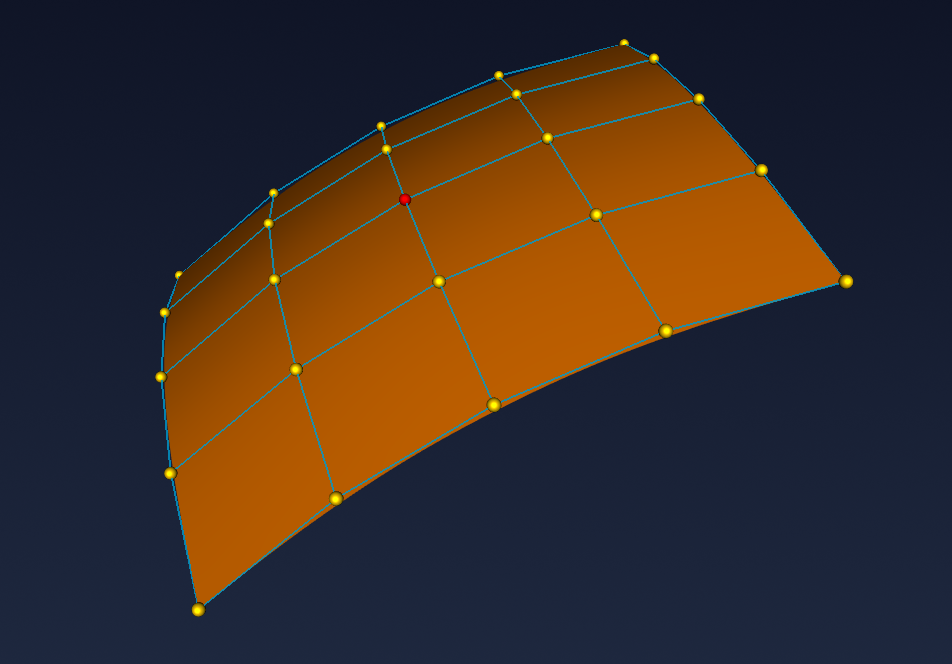
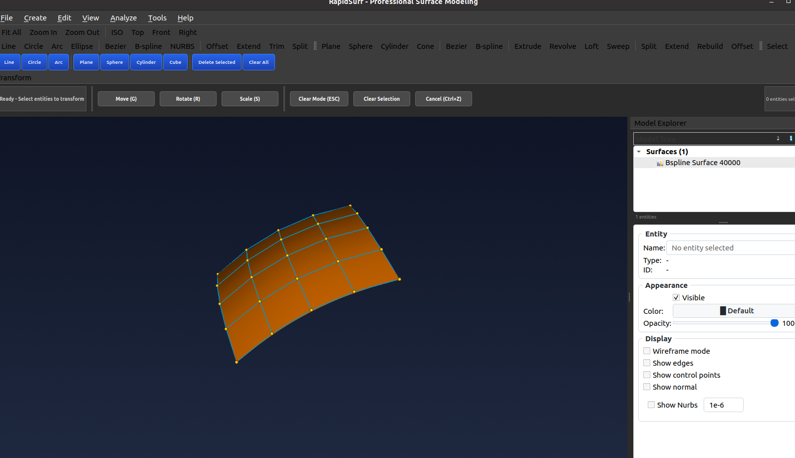
Control Points Display: When control points or control nets are visible in the viewport, it can be difficult to accurately pick curves and surfaces directly. The control points may interfere with entity selection.
Recommended Practice: Before performing "Pick from Viewport" operations, turn off the control points display by unchecking the "Show Control Points" option in the Display section of the right panel in the Model Explorer. This will ensure clean and accurate entity selection from the viewport.
Control Point Editing for Surfaces and Curves
Control point editing allows you to modify the shape of surfaces and curves by directly manipulating their control points. This powerful feature provides intuitive control over geometric shapes for precise design refinement.
-
Select the Control Point: Left-click on the control point you wish to edit to select it. The selected control point will be highlighted, indicating it's ready for manipulation.
-
Drag to Edit: Right-click and hold on the selected control point, then drag it to the desired position to adjust the shape of the surface or curve. You'll see real-time updates as you move the control point.
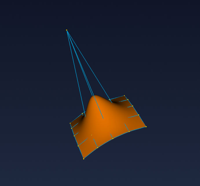
- Release and Finish: Release the right mouse button when you have finished dragging the control point to its new position. The geometry will update to reflect the new control point location.
- End Editing Mode: Right-click on an empty space in the viewport to deselect the control point and exit editing mode, finalizing your changes.
Local Transformation
Local transformation enables you to move, rotate, or scale selected objects using an interactive local coordinate frame. This feature provides precise control over object positioning and orientation in 3D space.
-
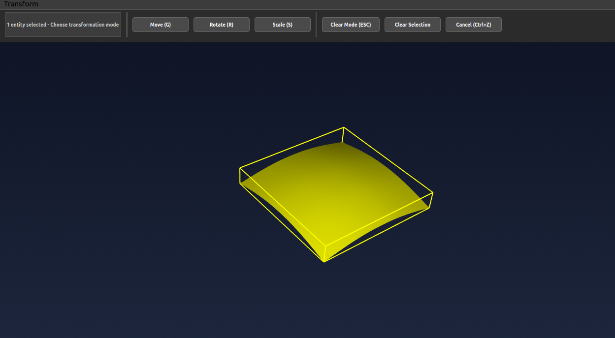
Select the Object: Left-click on the curve or surface object you want to transform to select it. The selected object will be highlighted.
-
Choose Transformation Action: Click on the desired transformation action (Move, Rotate, or Scale) from the toolbar to activate that transformation mode.
-
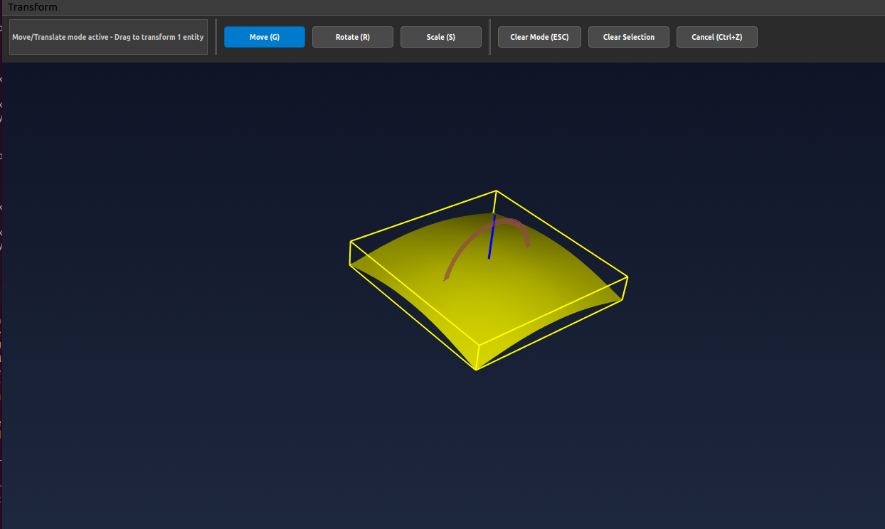
Display Local Frame: Click the selected object again to display the local coordinate frame, which shows the X, Y, and Z axes for precise transformation control.
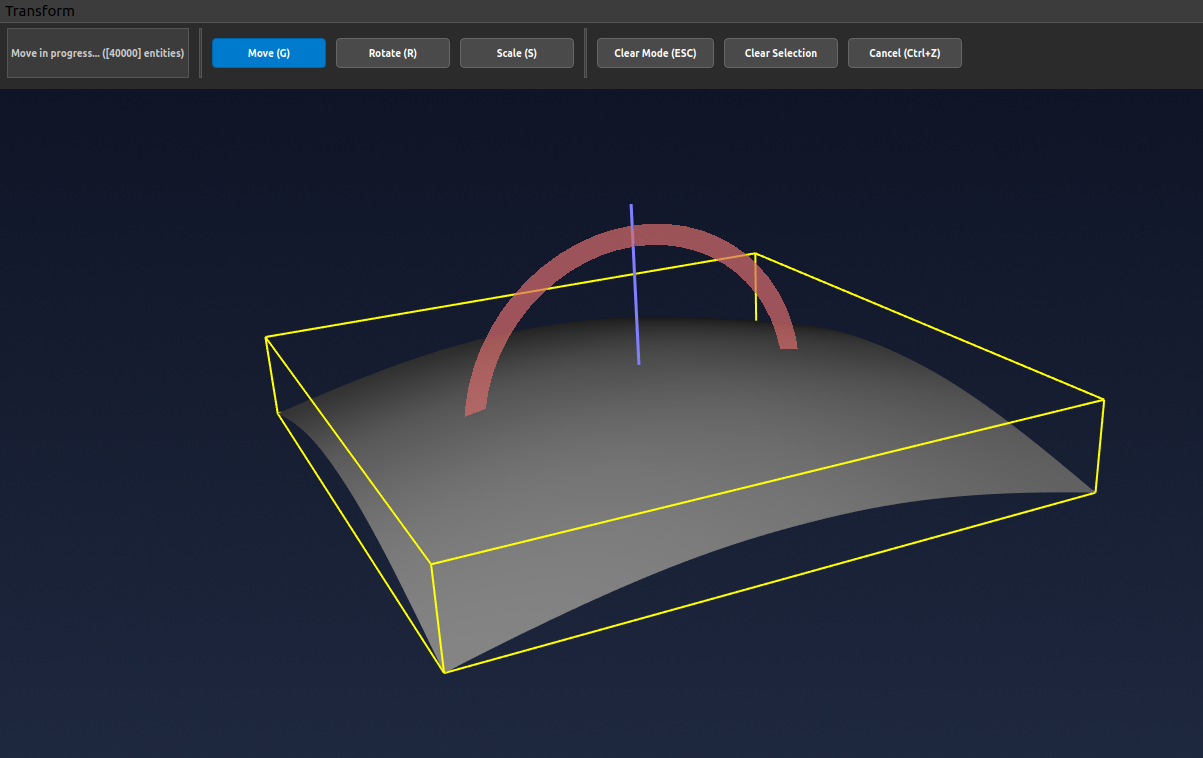
- Pick the Axis: Select the transformation direction by clicking on the desired axis (X, Y, or Z) of the local frame. The selected axis will be highlighted.
-
Move the Object: Left-click and hold on the selected axis, then drag to move, rotate, or scale the object along that direction. The transformation will update in real-time.
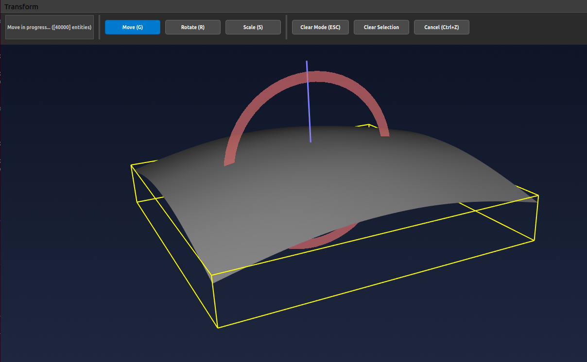
- Finish Transformation: When finished, click the "Clear Selection" and "Clear Mode" buttons to exit the transformation mode and finalize your changes.
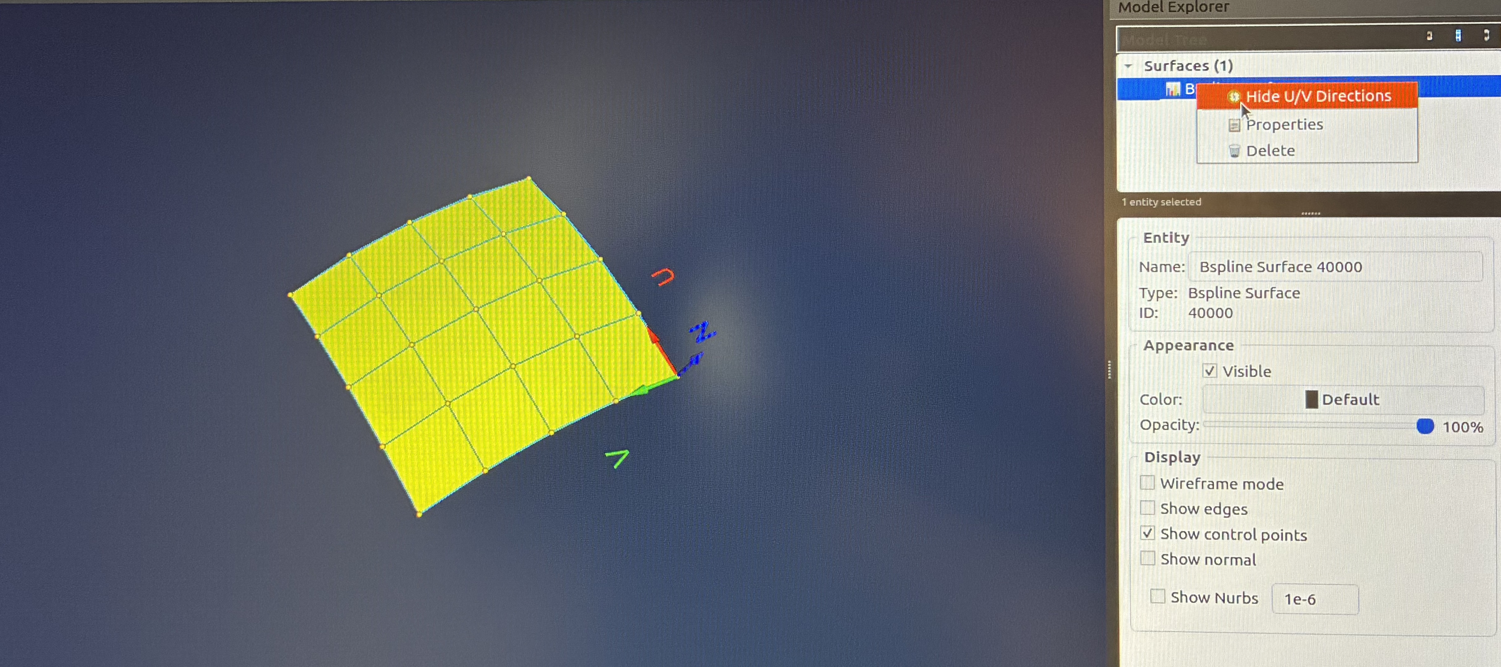
Show Surface UV Direction and Curve Start/End Direction
Display or hide the surface UV/Normal frame and curve start-to-end direction to better understand object orientation and parameterization. This visualization helps with surface analysis and boundary matching operations.
- Access Model Explorer: Open the Model Explorer panel to view the hierarchical list of all objects (curves and surfaces) in your current project.
-
Right-Click Object: Right-click on the desired surface or curve object in the Model Explorer to open the context menu with display options.
-
Toggle Visibility: Select the "Show/Hide Surface UV/Normal Frame" option for surfaces or "Show/Hide Curve Start to End Direction" option for curves to toggle the directional display on or off. The UV frame shows the surface parameterization and normal direction, while curve direction shows the parametric flow from start to end.
Important Notes
Selection: Ensure your object is properly selected before initiating any transformation or editing operation. Selected objects are highlighted in the viewport.
Viewport Navigation: Use the viewport navigation tools (orbit, pan, zoom) to adjust your perspective for better control during editing operations. Right-click and drag to orbit, middle-click to pan, and scroll to zoom.